Chapter 2 - Aircraft General Knowledge (AGK)
| Navigation: <- Previous Chapter 1 | Table of Contents | Chapter 2 | Next -> Chapter 3 |
These notes are exam-focused for CASA PPL AGK and aligned with FAA PHAK system knowledge where technically applicable. Use your aircraft POH/AFM as final authority for numbers, limitations, and procedures.
How to use this chapter
| Label | Meaning |
|---|---|
| CASA Primary | Your aircraft POH/AFM, CASA workbook exam conventions, Australian training context |
| PHAK Secondary | FAA PHAK Ch 7–8 for system and instrument theory — verify numbers and failures against POH |
Study habits: Build a failure indication table (pitot, static, vacuum, electrical) on one page. Sketch pitot vs static ports and what each instrument reads when blocked.
2.0 Terminology: POH and AFM
- AFM (Airplane/Aircraft Flight Manual): the approved flight manual containing aircraft-specific operating limitations, procedures, and performance data that pilots must comply with.
- POH (Pilot’s Operating Handbook): the manufacturer handbook used in day-to-day operations; for most light aircraft, the POH includes the approved AFM sections and is commonly referred to as the aircraft’s
AFM/POH. - Why this matters for exam and flight: if a generic rule conflicts with aircraft documentation, follow the approved
AFM/POH, placards, and limitations for that specific aircraft.
2.1 Airframe, Structure, and Flight Controls
PHAK Secondary: structure and control concepts. CASA Primary: POH limitations (Va, Vno, Vne, flap speeds).
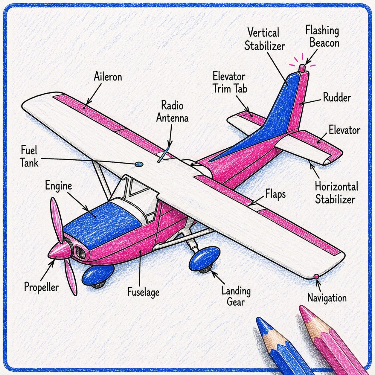
- Major airframe groups
- Fuselage: central structure that carries occupants, payload, and connects wings/tail; houses cockpit/cabin.
- Wings: generate lift; attach engines on many types; carry fuel tanks on many GA aircraft.
- Empennage: tail assembly—usually horizontal stabilizer (pitch stability) and vertical stabilizer (directional stability/yaw damping).
- Landing gear: supports aircraft on ground; absorbs loads on takeoff/landing (fixed or retractable).
- Engine mount: structure attaching engine to airframe; transmits thrust/vibration loads.
- Control surfaces: movable surfaces that change lift/drag/moment for control (primary and secondary).
- Primary controls (rotate aircraft about its axes—see PHAK flight controls chapter):
- Ailerons: trailing-edge wing surfaces that move differentially → roll about longitudinal axis.
- Elevator (or stabilator): horizontal tail surface(s) → pitch about lateral axis.
- Rudder: vertical tail surface → yaw about vertical axis.
- Secondary / high-lift / drag devices
- Flaps (plain / split / slotted / Fowler): extend camber and/or wing area → more lift and drag at low speed (takeoff/landing). Visual Reference (note the flap position is incorrect)
- Trim tabs (and related trim systems): small surfaces that reduce steady control forces so the pilot is not holding pressure continuously.
- Typical construction
- Semi-monocoque: loads carried by skin plus internal frames/stringers (common metal GA construction).
- Stressed skin: outer skin participates in carrying flight loads.
- Frames, stringers: circumferential/longitudinal stiffeners forming fuselage shape and strength.
- Spars, ribs: main wing beams (spar) and cross-section supports (rib) that define wing shape and carry bending/torsion.
- Structural terms
- Datum: reference plane/line for measuring arms in weight and balance.
- Stations / arms: distance from datum to each weight item (moment arm).
- Limit load: maximum load for normal operation certification basis; ultimate load: higher structural proof margin (typically 1.5× limit load conceptually—always use POH/AFM wording).
- Normal vs utility category: operating categories with different approved manoeuvre/weight limits—must match POH.
- Common failure risks
- Corrosion: metal loss from environment; inspect joints and drain holes.
- Fatigue cracking: cracks from repeated stress cycles; inspect high-stress areas per maintenance guidance.
- Buckling: thin panels failing under compression/shear.
- Control cable wear / hinge damage: can cause binding or restricted surface movement—preflight free movement checks.
References: FAA PHAK — Chapter 3: Aircraft Construction, FAA PHAK — Chapter 6: Flight Controls
Visual references (primary and secondary controls)
Primary flight controls (aileron, elevator, rudder):

Source page: Wikimedia Commons
Secondary/high-lift and drag devices on wing (flaps, slats, spoilers, etc.):

Legend:
- Winglet
- Low Speed Aileron
- High Speed Aileron
- Flap track fairing
- Krüger flaps
- Slats
- Three slotted inner flaps
- Three slotted outer flaps
- Spoilers
- Spoilers-Air brakes
Source page: Wikimedia Commons
Exam cues
- Know what each control does and opposite control combinations for coordinated turns.
- Understand flap effects on stall speed, drag, climb performance, and go-around behavior.
2.2 Piston Engine Fundamentals
- Four-stroke cycle (one thermodynamic cycle per two crankshaft revolutions per cylinder):
- Intake: piston descends, inlet valve open—air/fuel charge enters.
- Compression: valves closed, piston rises—pressure/temperature rise.
- Power: spark ignites mixture near TDC—expansion drives piston down.
- Exhaust: exhaust valve opens—burned gases expelled.
- Engine layout (typical light GA piston):
- Opposed cylinders: cylinders arranged on opposite sides of crankcase—often horizontally opposed flat engines.
- Crankshaft: converts reciprocating piston motion to rotary output (drives prop).
- Camshaft / valve train: controls intake and exhaust valve opening/closing timing.
- Spark plugs: ignite mixture each cycle (two plugs per cylinder common for redundancy).
- Power output factors
- Mixture strength: fuel-to-air ratio; affects power, cooling margin, and detonation margin (lean/rich per POH).
- RPM: revolutions per minute; with constant-speed prop, manifold pressure (MP) also defines power.
- Volumetric efficiency: how well cylinders fill with fresh charge (affected by induction design, altitude, throttle).
- Density altitude: non-standard temperature/pressure reduces mass airflow → less power.
- Detonation vs pre-ignition
- Detonation: abnormal rapid pressure rise after spark—can damage pistons/cylinder heads.
- Pre-ignition: mixture ignites before intended spark timing due to hot spot—often very destructive quickly.
- Both demand mixture/power adjustments and maintenance attention.
- Shock cooling risk: rapid power reduction can drop cylinder head temperatures (CHT) quickly; some POHs caution against abrupt cooling in descent—follow type guidance.
Induction systems
- Carburettor
- Venturi: narrows duct to speed airflow and lower pressure for fuel discharge.
- Fuel metering: jets/mixture control set fuel flow for throttle position and altitude.
- Throttle butterfly: restricts airflow to control manifold pressure/RPM.
- Mixture control: adjusts fuel flow at a given throttle (often pulled lean for cruise).
-
Fuel injection: meters fuel at injectors—typically better cylinder-to-cylinder distribution and no carb icing in the carb (induction icing can still occur at filter/throttle plate on some systems).
- Carb icing (induction ice in carb systems):
- Forms when moisture and cooling from fuel evaporation/vaporization chill the venturi.
- Often worst at partial throttle (partially closed butterfly).
- Symptoms: falling RPM (fixed pitch), rough running, MP drop (constant speed).
- Action: carb heat routes warm air to melt ice—expect temporary rougher running during clearing.
CASA Exam Cues — carburettor icing
- Ice can form at above freezing OAT when moisture is present (venturi cooling).
- Highest risk often partial power and high humidity — not only “cold day.”
- Classic signs: RPM drop (fixed pitch), rough engine, MP drop (constant-speed prop).
- Correct immediate action: full carb heat per POH; expect brief rougher running while ice clears.
- After recovery: apply heat as needed; monitor; consider exit from icing conditions.
- Fuel-injected types (e.g. many Diamond trainers): no carb ice, but induction/filter icing is still possible — do not answer “impossible” on exam.
- Exam trap: confusing carb ice with fuel starvation or magneto failure — ice usually builds gradually with power loss at constant throttle.
Ignition
- Magneto: self-contained ignition generator driven by engine—does not require aircraft electrical bus power for spark.
- Dual magnetos: two independent systems + two plugs per cylinder improve combustion and provide redundancy.
- Magneto check (run-up): verifies drop within POH limits—large/no drop can indicate faulty grounding/wiring/plugs.
Lubrication and cooling
- Engine oil: lubricates bearings/cam, cools pistons via jet/spray, cleans/contaminant suspension, seals, corrosion protection.
- Air cooling: cylinder fins plus baffles and cowl flaps (if fitted) direct cooling airflow.
- Trend monitoring: watch oil pressure/temperature and CHT/EGT together—not isolated snapshots.
References: FAA PHAK — Chapter 7: Aircraft Systems (powerplant, induction, ignition, oil)
Figure (four-stroke airflow overview): Wikimedia Commons — 4-stroke engine with airflows

2.3 Propellers
- Fixed-pitch propeller: blade angle fixed by manufacture—simple, lighter; power absorbed varies strongly with airspeed/RPM.
- Climb prop: lower pitch—better climb/acceleration; typically lower cruise speed at same RPM.
- Cruise prop: higher pitch—better cruise efficiency; often weaker climb margin.
- Constant-speed (variable-pitch) propeller: governor changes blade angle to maintain pilot-selected RPM as load changes.
- Fine pitch / low blade angle: lower blade AoA—typically higher RPM capability at low speed (takeoff/climb context).
- Coarse pitch / high blade angle: higher blade AoA—typically holds cruise RPM with lower tip speeds / better efficiency.
- Key terms
- Blade angle: angle between blade chord and plane of rotation (often controlled via governor).
- Geometric pitch: theoretical distance blade would move forward per revolution if in solid medium (idealized).
- Effective pitch: actual advance per revolution after losses—related to slip (propeller not screwing through air perfectly).
- Operational considerations
- Overspeed: RPM exceeds limit—reduce power/pitch per POH immediately.
- Control sequence: throttle → mixture → propeller order varies by POH—always follow AFM.
- Avoid prohibited combinations: many POHs chart RPM × manifold pressure regions that damage engine.
References: FAA PHAK — Chapter 7: Aircraft Systems (propellers)
Figure (propeller blade angle / terminology): Wikimedia Commons — Propeller blade AOA (adapted from FAA PHAK figures)

2.4 Fuel System and Fuel Management
Real-world application
Most fuel emergencies in training are selection or management errors, not empty tanks — preflight sample, correct tank, and timed consumption beat guessing from a sticky gauge.
CASA Primary: POH fuel system diagram and limitations. PHAK Secondary: general fuel system components.
- Typical components
- Fuel tanks: store usable fuel; know usable vs unusable per POH.
- Vents: equalize tank pressure with atmosphere—blocked vent can cause feed failure or structural stress.
- Fuel selectors / valves: route fuel from selected tank(s) to engine; incorrect position → starvation.
- Strainers / filters: trap debris; blocked filter reduces flow—follow inspection/replacement schedule.
- Sumps / drains: lowest points for water/sediment sampling—preflight until clean sample.
- Pumps: engine-driven primary pump (often); electric auxiliary boost on many types for priming/takeoff/climb/emergency.
- Lines: rigid/flexible plumbing—inspect for leaks, chafing, security.
- Gauges: often permissive indication—cross-check with visual/timed consumption per POH.
- Metering to engine: fuel injection or carburettor delivers metered fuel to cylinders.
- Fuel contamination
- Water: heavier than AVGAS—settles in sumps; dangerous if ingested.
- Sediment / rust: from tanks/lines—can block filters/injectors.
- Microbial growth: more common in jet fuel storage; still understand contamination risk for training.
- Fuel grade / type discipline
- Use only grades stated in POH/placards (AVGAS vs Jet-A confusion is catastrophic—different engines).
- Fuel starvation vs fuel exhaustion
- Starvation: fuel remains but engine starved (wrong selector, blocked vent, pump failure, blocked line).
- Exhaustion: usable fuel consumed—planning error.
- Balancing and feed management
- Switch tanks per POH for lateral balance and reliable feed.
- Some POHs warn against certain attitudes with low fuel—follow explicitly.
CASA exam-relevant points
- CASA workbook uses AVGAS specific gravity 0.72 kg/L in loading/fuel calculations.
- Fuel planning questions may reference CASR Part 91 MOS day VFR fuel policy.
- In exam scenarios, read whether operation assumptions are Part 91/other as stated.
References: FAA PHAK — Chapter 7: Aircraft Systems (fuel systems), CASA workbook
2.5 Electrical System
- Battery: chemical storage for starting and emergency/bus support; typically 12 V or 24 V DC in GA.
- Alternator / generator: alternator is most common on modern GA—produces AC converted to DC at higher efficiency than old generators; provides primary electrical power in flight.
- Voltage regulator: maintains bus voltage within limits as electrical load changes.
- Bus bars: electrical “distribution rails” feeding avionics, lights, pumps—often split essential vs non-essential conceptually.
- Circuit breakers / fuses: protect wiring from overcurrent—reset breakers only once per POH guidance (avoid repeated cycling faults).
-
Master / avionics switches: master connects battery/alternator to electrical system; avionics master often delays power-on spikes.
-
System types: direct current (DC) typical for light aircraft.
- Failure indications
- Ammeter / loadmeter: shows charge/discharge abnormal patterns.
- Low voltage annunciator: warning of bus voltage decay.
- Avionics degradation: dropped radios/autopilot may indicate partial electrical failure.
- Typical actions (always POH-specific)
- Load shedding: turn off non-essential consumers to preserve battery.
- Alternator reset: only if POH permits procedure.
- Land as soon as practical if unable to restore charging—battery time is finite.
CASA Exam Cues — electrical failures
- Magnetos still provide spark on most piston trainers — engine can run with total electrical failure, but radios/lights/gyro suction pump (if electric-driven on some types) may not.
- Ammeter/loadmeter abnormal → suspect alternator; load shed non-essentials per POH.
- Glass cockpit (Diamond DA40/DA42): electrical failure may affect PFD/MFD/AHRS — know backup instruments and reversionary mode in POH.
- Cessna 172 (typical): vacuum pump often engine-driven — electrical loss may not stop vacuum immediately, but electric turn coordinator (if fitted) and avionics fail as buses deplete.
- Exam trap: assuming you must land immediately on any electrical warning — follow POH; battery endurance is limited.
- Know difference: alternator failure (may reset once) vs battery exhaustion (no charging).
References: FAA PHAK — Chapter 7: Aircraft Systems (electrical)
2.6 Gyroscopic Instruments (Vacuum, Electric, and Glass)
Definition — gyroscopic instrument: flight instrument using a spinning rotor (or solid-state equivalent) with rigidity in space and precession to display attitude, heading, or turn rate.
Gyroscopic principles
| Principle | Meaning | Instrument use |
|---|---|---|
| Rigidity in space | Spin axis stays fixed in space as aircraft moves around it | Attitude indicator, heading indicator |
| Precession | Applied force appears 90° around spin axis | Turn instrument design; limits on AI handling |
Classic vacuum-driven gyros (typical Cessna 172 analogue panel)
| Instrument | Display | Failure if vacuum lost | Notes |
|---|---|---|---|
| Attitude indicator (AI) | Pitch and bank vs horizon | Tumbles / unreliable | Suction typically 4.5–5.5 inHg range (POH) |
| Heading indicator (HI/DG) | Magnetic heading (drifts) | Unreliable | Reset from compass in straight, level, unaccelerated flight |
| Turn coordinator | Rate of turn + slip/skid ball | Often electric on later 172s — may still work | Key partial-panel instrument |
- Vacuum source: engine-driven vacuum pump → manifold suction to AI and HI.
- Low vacuum flag / gauge: treat AI/HI as unreliable; partial panel procedures apply.
Electric gyros and glass systems (typical Diamond DA40 / DA42)
| System | Typical fit | Failure mode awareness |
|---|---|---|
| Electric AI / turn coordinator | Backup or primary on some aircraft | Electrical bus failure |
| AHRS | Attitude/heading data to PFD | Sensor or power failure → reversionary instruments |
| ADC | Air data from pitot-static to displays | Pitot-static errors affect glass ASI/altitude |
- Diamond trainers: commonly integrated glass with standby analogue ASI, altimeter, attitude, compass — know your POH reversionary mode (which instruments remain primary).
- Exam focus: failure logic is the same as analogue — validate unusual indications, cross-check, partial panel.
Gyro failure modes (summary)
| Failure | Typical indication | Affected instruments |
|---|---|---|
| Vacuum pump failure | Low suction; AI/HI flag | AI, HI |
| Electrical failure | Bus voltage low; blanks | Electric TC, glass displays |
| Vacuum leak | Gradual AI/HI degradation | AI, HI |
| AHRS/ADC fault | Caution flags; conflicting data | Glass PFD |
CASA Exam Cues — vacuum / gyro failures
- Low vacuum → do not trust AI or HI; use partial panel scan.
- Turn coordinator (and compass) often remain core references on 172-style panels.
- HI drifts even when serviceable — must be periodically aligned to compass.
- If AI failed but pilot presses on in IMC/night: links to spatial disorientation (Chapter 4.4 — the leans, graveyard spiral).
- Diamond/glass: know backup / reversionary flight instruments; exam may describe “red X” or failed PFD — answer with POH logic, not airline procedures.
- Exam trap: turn coordinator shows rate of turn, not bank angle directly — do not treat as full attitude substitute.
Partial panel recovery (conceptual — always POH-specific)
Definition — partial panel: flight with one or more primary gyro instruments inoperative; rely on limited remaining instruments and outside cues when VMC.
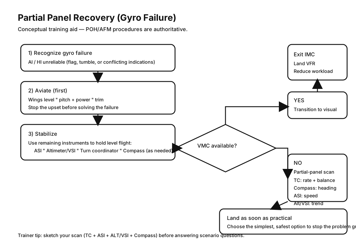
How to read the diagram (exam-friendly)
| Step | What you do | Why |
|---|---|---|
| 1 | Recognize AI/HI unreliable | Stops you “chasing” false attitude/heading |
| 2 | Aviate: wings level, pitch + power, trim | Buy time; stop the upset |
| 3 | Stabilize on remaining instruments | Reduce workload and error rate |
| 4 | If VMC: transition visual and land | Safest simplification |
| 5 | If not VMC: fly a disciplined partial-panel scan | Maintain control until landing option |
Ask yourself: What does your instrument panel tell you right now — which instrument is lying, and which ones still agree?
| Remaining instrument | Use in partial panel |
|---|---|
| Turn coordinator | Rate of turn; coordinate ball |
| Magnetic compass | Heading (errors in turns — Ch 2.8) |
| ASI | Airspeed control |
| Altimeter / VSI | Level and climb/descent (if static system serviceable) |
Human factors link: vestibular illusions (the leans, somatogravic) when outside visual cues are poor — see Chapter 4 — section 4.4 Spatial disorientation. Trust validated instruments only; do not fight false sensations.
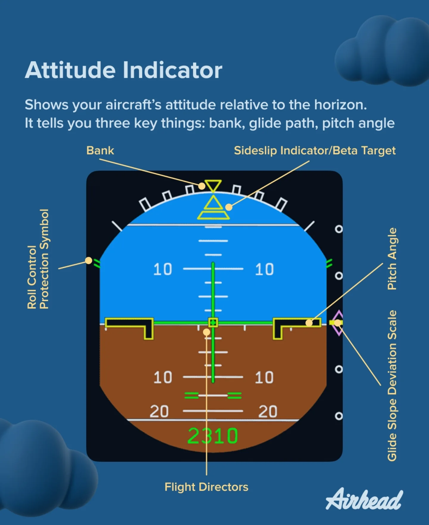
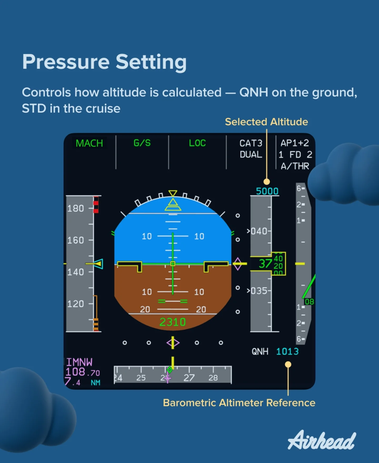
Glass cockpit awareness (reference)
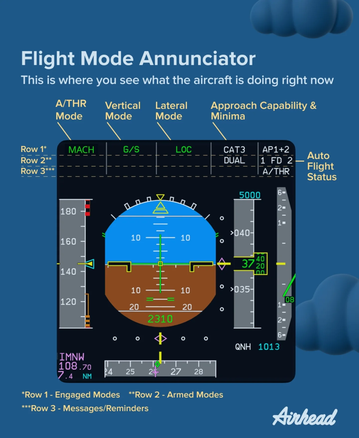
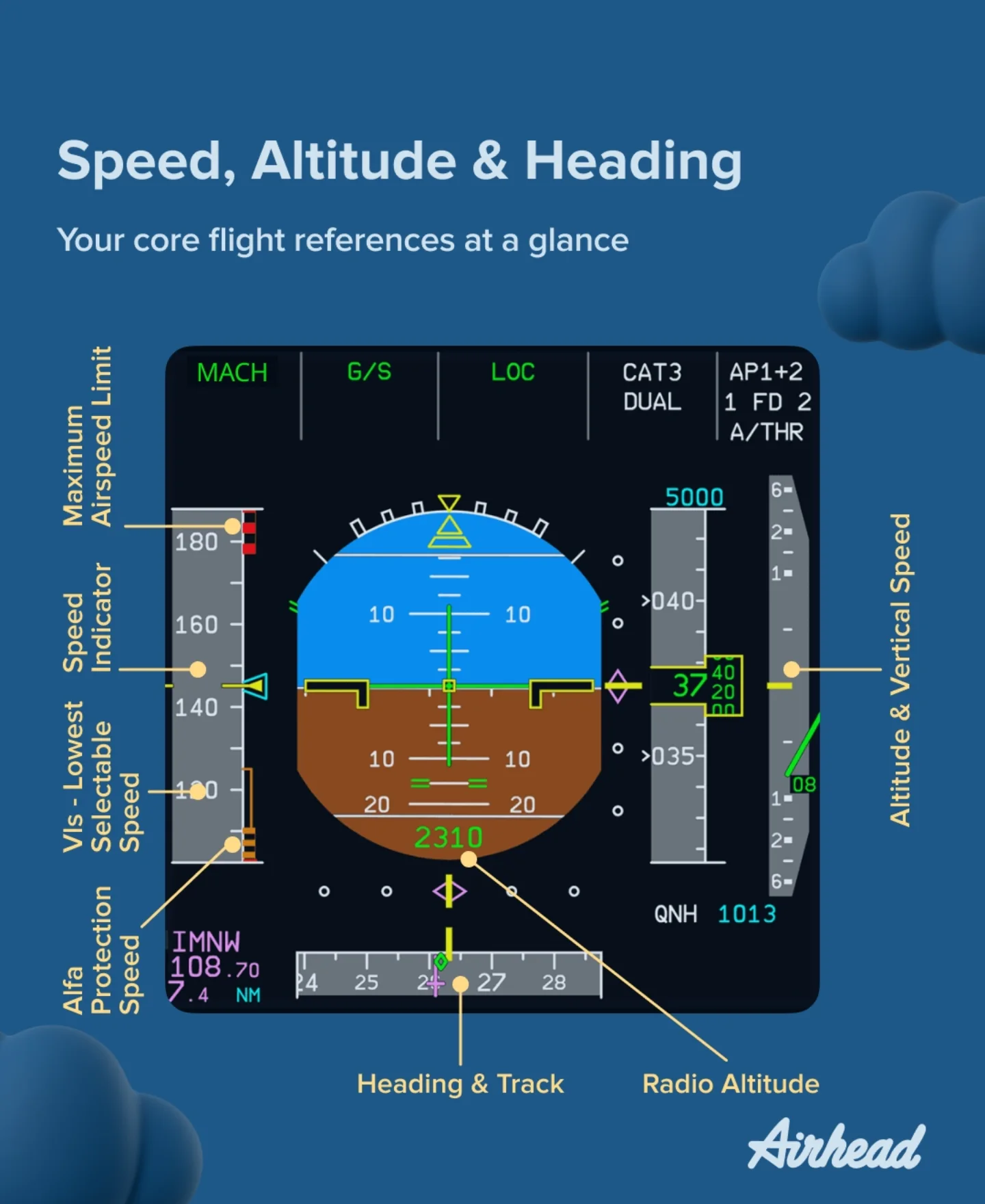
- PFD / MFD: integrated display; failure may switch to reversionary or standby steam gauges.
- Large-aircraft example (systems logic only): Airbus PFD layout for attitude guidance context.
References: FAA PHAK — Chapter 8: Flight Instruments
2.7 Pitot-Static Instruments and Errors
Why this matters
Partial-panel and blockage scenarios are core AGK — examiners expect you to name which instrument lies and what you trust next.
Ask yourself: Static blocked — altimeter frozen, VSI zero, ASI wrong in climb/descent. What does the attitude indicator still tell you?
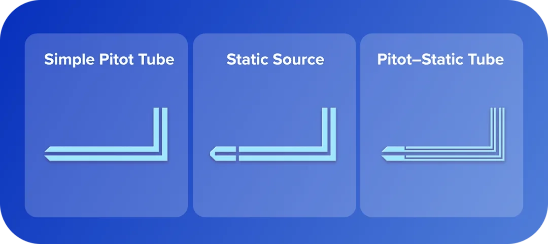
Definition — pitot-static system: uses pitot pressure (ram + static) and static pressure (ambient) to drive ASI, altimeter, and VSI.
PHAK Secondary: failure logic below. CASA Primary: your POH alternate static and partial-panel procedure.
Instrument operation
| Instrument | Pressure source | Displays |
|---|---|---|
| Airspeed indicator (ASI) | Pitot total vs static (diaphragm) | IAS (dynamic pressure) |
| Altimeter | Static only (aneroid) | Height per subscale (QNH) |
| VSI | Rate of change of static | Climb/descent rate (lags) |
Pitot, static, and combined sources:


Pitot-static failure modes and indications
| Blockage / fault | ASI (typical) | Altimeter | VSI |
|---|---|---|---|
| Pitot blocked, drain closed | Increases in climb, decreases in descent | Normal | Normal |
| Pitot blocked, drain open | Reads zero | Normal | Normal |
| Static port blocked | Under-reads in climb, over-reads in descent | Frozen | Zero |
| Pitot and static blocked | All three can appear frozen | Frozen | Frozen |
Alternate static source
Definition — alternate static source: cabin (or other backup) pressure fed to static instruments when primary external static port is blocked or suspected failed.
| Topic | Typical training aircraft notes |
|---|---|
| Cessna 172 | Pull alternate static knob (cabin air); static pressure in unpressurized cabin often lower than outside → altimeter reads higher, ASI higher, VSI may show climb momentarily |
| Diamond DA40/DA42 | POH procedure for alternate / standby static if fitted — confirm type |
| Purpose | Restore usable static pressure when external port blocked (water, ice, tape, wasp nest) |
| Exam trap | Forgetting instruments are wrong immediately after selecting alternate — note errors in POH |
CASA Exam Cues — alternate static source
- Used when primary static blocked or suspect (ice, contamination, damage).
- Cabin alternate static → instruments often indicate higher altitude and higher airspeed than actual (unpressurized cabin).
- VSI may show climb briefly when alternate selected — know POH correction if exam gives numbers.
- Does not fix pitot-only blockage — ASI still wrong if pitot blocked and drain closed.
- After use: maintain conservative margins; land and have system inspected.
Partial panel with pitot-static failures
| Failure | Still usable (often) | Pilot action |
|---|---|---|
| Pitot blocked | Altimeter, VSI (if static OK); compass; TC | Fly attitude/ power settings; pitch for known IAS if trained; land |
| Static blocked | ASI wrong; altimeter/VSI wrong | Select alternate static per POH; cross-check GPS/terrain; land |
| Both blocked | Very limited | Treat as emergency; VMC landing; no IMC continuation |
Human factors link: false climb/descent sensations if instruments misread — cross-check with Chapter 4 (sections 4.3 visual illusions, 4.4 spatial disorientation). Black-hole and false horizon approaches worsen when ASI/altimeter unreliable.
Airspeed terminology
| Name | Meaning | Typical usage |
|---|---|---|
| Indicated Airspeed (IAS) | Direct instrument reading before corrections | Primary reference for V-speeds and flying by the ASI |
| Calibrated Airspeed (CAS) | IAS corrected for position/instrument error (POH tables) | Performance chart inputs/outputs when POH specifies CAS |
| Equivalent Airspeed (EAS) | CAS corrected for compressibility | Higher-speed/altitude corrections (more relevant beyond basic GA regime) |
| True Airspeed (TAS) | Actual speed through the air mass; increases vs IAS with altitude (lower density) | Enroute performance and navigation computations |
| Ground Speed (GS ) | TAS adjusted for wind | ETA/ETE, nav log timing, and range over the ground |
Instrument/position errors
- Position error: static port location and flow field cause static pressure to differ from free stream.
- Density / compressibility: at high speed/altitude, ASI interpretation needs POH conversion to TAS.
- Lag / hysteresis: especially VSI — momentarily misleading during abrupt zoom/climb transitions.
- Pitot heat (if fitted): used in visible moisture near freezing — know POH; blocked heated pitot still dangerous.
References: FAA PHAK — Chapter 8: Flight Instruments
2.8 Magnetic Compass and Turning/Acceleration Errors
-
Magnetic compass: aligns with Earth’s magnetic field, not geographic (true) north—subject to aircraft acceleration and turning errors.
-
Variation (magnetic variation / declination): angular difference between true north and magnetic north at a location—shown on charts as isogonals.
-
Deviation: compass error caused by local magnetic fields in the aircraft (wiring, ferrous structure)—corrected by compass correction card mounted near compass.
- Turning error (dip-related) — Southern Hemisphere mnemonic UNOS:
- Undershoot headings near North, Overshoot headings near South when rolling into/out of turns from compass-only references.
- Acceleration error — Southern Hemisphere mnemonic ANDS:
- Accelerate while near North headings→ compass tends to show turn toward East; Decelerate→ tendency toward West (conceptual exam framing—always verify with groundschool references).
- Oscillation / lag: compass swings in turbulence; dip increases toward poles—use stabilized headings and periodic DI alignment.
References: FAA PHAK — Chapter 8: Flight Instruments (magnetic compass)
Figure (compass errors overview): see compass turning/acceleration illustrations in PHAK Chapter 8.
2.9 Landing Gear, Brakes, and Hydraulics
- Landing gear configuration
- Tricycle gear: nosewheel steering typical—more directional stability on ground for most students.
- Tailwheel (conventional): mains forward of CG—requires specialized technique (PIO, ground-loop risk).
- Fixed gear: always extended—lower complexity; more drag.
- Retractable gear: reduces drag—adds extension/retraction system, warnings, and emergency procedures.
- Brakes
- Common GA setup: hydraulic disc brakes on mains.
- Toe brakes: independent left/right braking for steering on ground (differential braking).
- Risks
- Brake fade / overheating: prolonged riding brakes after heavy landing or taxi downhill.
- Parking brake: verify released before takeoff (critical checklist item).
- Hydraulic leaks / soft pedal: abnormal braking—may indicate leak or air in system—follow POH.
- Retractable extras
- Extension: normal electric/hydraulic/manual modes per type.
- Warnings: horn/light—“gear unsafe” cues must be understood.
- Emergency extension: gravity/manual valve procedures—memory items in many POHs.
References: FAA PHAK — Chapter 7: Aircraft Systems (landing gear, hydraulics)
2.10 Environmental, Ice/Anti-Ice, and Oxygen Basics
-
Cabin heating (many piston singles): often muff/shroud around exhaust heats cabin air—carbon monoxide (CO) can leak from cracked exhaust/muff—know CO symptoms (headache, nausea, confusion) and shut off heat / ventilate / land.
-
Ventilation / demist: ram air / cabin vents reduce humidity on windshield—critical for visibility in rain/humidity.
- Ice categories affecting flight
- Induction icing: blocks/reduces airflow to engine (carb ice, filter ice, alternate air doors).
- Airframe icing: accumulates on wings/tail—destroys lift and increases weight/drag.
- Instrument icing: pitot/static blocked—airspeed/altitude misleading.
-
Anti-ice vs de-ice
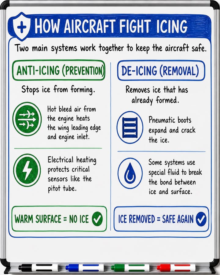
- Anti-ice: systems activated before ice accretion in known icing exposure (typically turbine/airliner philosophy; light GA often emphasized avoidance).
- De-ice: removes ice after accumulation (boots, weeping wing fluid—mostly larger aircraft; light GA often limited capability).
- Supplemental oxygen (if installed): understand hypoxic thresholds for prolonged high-altitude legs and fire risk around oxygen equipment—follow POH.
References: FAA PHAK — Chapter 7: Aircraft Systems (environmental/icing concepts)
2.11 AFM/POH Knowledge You Must Know for Exam and Flight Test
Typical AFM/POH section layout (terminology varies slightly by manufacturer):
- Section: Limitations (must-know for every flight)
- Airspeed limitations: V-speeds (see elaboration below) and color-coded arcs on the ASI.
- Powerplant limits: max RPM, manifold pressure, oil pressure/temperature, CHT/EGT limits if listed.
- Weight limits: MTOW, max landing weight, max zero fuel weight, compartment limits.
- CG envelope: approved center of gravity range; Normal vs Utility category limits if applicable.
About V-speeds
All numerical values are aircraft-specific. Memorize concepts and where to look them up; never use generic numbers on a checkride or in flight—only your POH/AFM and placards.
Naming: V = velocity (knots IAS in US/POH convention unless the POH states otherwise). Subscripts describe configuration or flight phase.
| Symbol | Common name | Meaning | Cessna 172S Skyhawk example (KIAS) |
|---|---|---|---|
| VS | Stall speed (general) | Minimum steady flight speed at which the aircraft is controllable in the stated condition (stall warning may occur slightly before). | See VS0 and VS1 (POH defines by configuration). |
| VS0 | Stall speed, landing config | Stalling speed in landing configuration (e.g., gear down if retractable, flaps at landing setting—per POH). | 40 KIAS (full flaps, max gross, power off). |
| VS1 | Stall speed, specified config | Stalling speed in a defined configuration—often “clean” or a stated flap setting; POH defines exactly which. | 48 KIAS (flaps up, max gross, power off). |
| VFE | Max flap extended speed | Do not exceed this IAS with flaps extended to the associated position(s); risk of overload or loss of control authority. | 110 KIAS (10 deg), 85 KIAS (more than 10 deg). |
| VX | Best angle of climb speed | Speed giving greatest altitude gain per unit of horizontal distance—used for obstacle clearance after takeoff when POH recommends it. | 62 KIAS (sea level, max gross). |
| VY | Best rate of climb speed | Speed giving greatest altitude gain per unit of time—used for routine climb when obstacle clearance is not limiting. | 74 KIAS (sea level, max gross). |
| VLE | Max landing gear extended speed | Safe speed with gear extended (retractables). | N/A (fixed gear). |
| VLO | Max landing gear operating speed | Safe speed to extend or retract gear (sometimes split into separate extend vs retract limits in POH). | N/A (fixed gear). |
| VA | Maneuvering speed | Below this speed (at or below max gross weight per POH), full abrupt control deflection should not exceed limit load factor—still avoid abusive inputs. Often decreases at lighter weight (see POH). | 105 KIAS at 2550 lb (decreases at lower weight). |
| VNO | Maximum structural cruising speed | Upper limit of the green arc; do not deliberately fly in rough air above VNO unless authorized by POH for smooth air only (yellow arc rules). | 129 KIAS. |
| VNE | Never-exceed speed | Red radial line—do not exceed under any circumstances; structural/red-line limit. | 163 KIAS. |
| Vref | Landing reference speed | used for final approach, ensuring a safe, stable landing. Equals to VS0 x 1.3 | 52 KIAS |
| Best glide | Best glide / minimum sink (terms vary) | Speed for maximum distance or minimum descent rate in power-off glide—POH may list separate “best glide” and “minimum sink”; names vary by manufacturer. | 68 KIAS (commonly used best-glide speed). |
Example values shown are for quick study context and can vary by model/year/configuration and weight. Always use the exact aircraft POH/AFM and cockpit placards for operation.
KIAS = Knots Indicated Airspeed
Multi-engine (awareness for theory): VMC / Vmca is minimum control speed with one engine inoperative—primarily multi-engine training; your POH if applicable.
Air Speed Indicator (ASI) color bands
| Arc / mark | Typical meaning |
|---|---|
| White arc | Full-flap operating range (lower end ~ VS0, upper end VFE). |
| Green arc | Normal operating range (low end often VS1 clean at gross, high end VNO). |
| Yellow arc | Caution range—smooth air only; no abrupt maneuvers; understand POH wording for flight in turbulence. |
| Red radial line | VNE—never exceed. |
Operational reminders
- Flaps: observe VFE before extending further; plan configuration changes ahead of dot / limiting speed.
- Turbulence: slow toward rough-air / maneuvering guidance in POH; never chase VNE in downdrafts.
- Approach speeds: POH may publish approach/climb speeds as checklist speeds (not always labelled with formal V-speed symbols)—still limitations.
References: FAA PHAK — Chapter 8: Flight Instruments (airspeed indicator markings), FAA PHAK — Chapter 11: Aircraft Performance (Vx, Vy, glide), FAA PHAK — Chapter 9 (where limits live in POH)
- Normal / abnormal / emergency procedures
- Memory items: immediate actions (fire, engine failure) performed then checklist expanded.
- Checklists: configure aircraft systematically—follow POH sequencing.
- Performance charts
- Takeoff/landing: ground roll vs obstacle clearance distances—apply wind, slope, surface, density altitude corrections per POH order.
- Climb/cruise: ROC, fuel flow, range/endurance—temperature/weight sensitive.
- Systems descriptions
- Fuel: usable/unusable fuel, tank sequencing, pump usage.
- Electrical: buses, alternator/battery failure modes.
- Hydraulic/pneumatic: gear/flaps/brakes as applicable.
- Supplements: STC mods (avionics, tanks) may change limits—must be onboard.
High-value memory set
- All relevant V-speeds for your training type.
- Fuel system capacities and unusable fuel.
- Oil limits, CHT/EGT limits (if listed), and key caution ranges.
References: FAA PHAK — Chapter 9: Flight Manuals and Other Documents, FAA PHAK — Chapter 10: Weight and Balance, FAA PHAK — Chapter 11: Aircraft Performance
2.12 Weight and Balance Link to AGK
- Moment: rotational tendency of a weight about the datum; computed as weight $\times$ arm:
-
Arm: horizontal distance from datum to an item’s center of gravity (often inches or mm per POH).
-
CG (center of gravity): average location of aircraft mass; CG position must remain inside approved envelope.
-
Basic Empty Weight (BEW): aircraft empty weight including fixed equipment and fluids per weighing specification—often includes unusable fuel and full oil per weighing notes—always read POH weight schedule wording.
-
Envelope: graph/table defining permissible combinations of weight vs CG.
-
Operational impacts
- Forward CG: more nose-heavy—often higher stall speed trend, heavier elevator forces, longer takeoff roll for rotation.
- Aft CG: closer to aft limit—lighter control forces but reduced stability margin and stall recovery characteristics—must remain legal.
References: FAA PHAK — Chapter 10: Weight and Balance
2.13 Key Definitions and Practical Examples
- Detonation: abnormal, explosive combustion after normal ignition, causing high thermal/mechanical stress.
- Reference: engine operational limits / mixture guidance — FAA PHAK — Chapter 7.
- Example: high power with improper mixture/cooling in hot conditions can increase risk.
- Pre-ignition: mixture ignites before spark due to a hot spot.
- Reference: FAA PHAK — Chapter 7.
- Example: fouled/damaged plug or overheated component can trigger early ignition and rapid temperature rise.
- Fuel starvation: fuel onboard but not reaching engine.
- Reference: fuel system faults / mismanagement — FAA PHAK — Chapter 7.
- Example: incorrect tank selection after switching or blocked vent.
- Fuel exhaustion: usable fuel depleted.
- Reference: flight planning — FAA PHAK — Chapter 11; CASA fuel policy context in CASA RPL/PPL/CPL Aeroplane Workbook.
- Example: inaccurate fuel planning plus headwind leads to empty selected tank and engine stoppage.
- Static source blockage: loss of correct static pressure feed to instruments.
- Reference: pitot-static failures — FAA PHAK — Chapter 8.
- Example: altimeter freezes and VSI reads zero; ASI behavior becomes misleading in climb/descent.
Scenario: carb icing recognition
- Cruise at moderate power in humid conditions; RPM slowly falls and engine feels rough.
- Correct action: apply full carb heat, expect temporary roughness/power drop, monitor recovery, then reassess power/settings.
2.14 Pre-Exam Revision (Must Know · Nice to Know · Common Traps)
Sketch it: One page — pitot/static blockage table, vacuum failure indications, carb ice flow (carburettor aircraft only).
Must know
- ASI, altimeter, VSI operation and pitot/static blockage indications; alternate static effects.
- Partial panel and gyro failures (link Chapter 4).
- Carb icing recognition and immediate actions (carburettor aircraft); fuel grade and sump checks.
- Electrical vs engine power (magnetos); fuel starvation vs exhaustion.
- Detonation vs pre-ignition; fixed vs constant-speed propeller basics.
- POH limits: V-speeds, flap speeds, crosswind, fuel system.
Nice to know
- Glass/AHRS vs vacuum gyro contrast at POH level.
- Southern Hemisphere compass turning/acceleration errors.
- Landing gear, hydraulics, environmental/anti-ice overview.
- Basic W&B moment arm concept (detail in Chapter 3).
Common traps
- Confusing fuel quantity with fuel feed/selection.
- Misreading ASI/static blockage scenarios.
- Forgetting alternate static changes indications (often higher alt/IAS).
- Treating turn coordinator as a full attitude indicator.
- Assuming electrical failure always stops the engine (magnetos).
- Applying carb heat to fuel-injected aircraft without reading scenario.
- Forgetting density altitude effects on engine, prop, and wing together.
- Applying generic numbers instead of aircraft-specific POH values.
References
CASA Primary
- CASA RPL/PPL/CPL Aeroplane Workbook
- Aircraft POH/AFM (limitations and emergencies)
PHAK Secondary / supplementary
- FAA PHAK (full handbook)
- FAA PHAK — Chapter 7: Aircraft Systems
- FAA PHAK — Chapter 8: Flight Instruments
- FAA PHAK — Chapter 9: Flight Manuals
- CASA Day VFR syllabus
- CASA VFRG example PDF (training support, not legislation)
| Navigation: <- Previous Chapter 1 | Table of Contents | Chapter 2 | Next -> Chapter 3 |
IMPORTANT: Always verify with current official publications.
prepared by Raptor K, a guy learning to fly (feel free to contact me via IG: @raptorkwok or Email)